Modification of an Icom 751 for better CW full break-in operation
I recently worked on my Icom 761 and got out the 751 (not an A
model). I have become involved in CW traffic handling and
currently am the Kansas NTS CW Traffic Manager. The 751 really
leaves a lot to be desired in full break-in mode. It has a
terrible "thump" when switching in and out of transmit mode. In
fact, it is so bad I couldn't use it this way. This article does
not apply to the Icom 751A.
I dug out the schematic and began looking at the differences
between the 751 and the 745 thinking it might be the same. I had fixed my
745 from "thumping" by replacing most of the CW audio amp electrolytics
and putting additional large electrolytics on the CW lead at the
switching point for activating the CW lead. Anyway, no such luck
on the 751. It used an entirely different scheme.
I didn't see anything right away so I ordered a batch of
electrolytics and a new audio amp thinking this might help. The
751 required turning the volume control almost to 12 o'clock before
getting any hearable volume so I thought maybe something was wrong
here.
I replaced all the electrolytics associated with the audio path,
i.e. after the detector stage and the audo amp. I couldn't really
hear any difference but at least I felt better.
At this point, I dug out the scope and started looking at where the
thumping was coming from. The 751 uses two electronic switches
(IC7 C and D) to mute the audio, one for the actual audio and one for
the monitor/sidetone circuit. The scope indicated that maybe
these were causing the pulses generated when they were switched. (I
should have realized at this point that this wasn't the case because
when switching to transmit a large positive pulse occured and when
switching back to recieve a large negative pulse was generated. I
figured out later what was happening.) Anyway, I started cutting
traces and adding jumpers and effectively bypassed the electronic
switches. What I ended up doing was connecting the monitor and
audio stages to the audio amp with no switching. This basically
fixed the problem but I lost the use of squelch and the volume was
reduced quite a bit. So I started looking elsewhere.
A couple of things I learned was that the electronic switches were
not needed for cw operation. The receiver mutes very well without
them and the monitor/sidetone only works when the key is down.
This is exactly what was needed. The electronic switches
are really only needed for squelch operation but the circuit designers
built the 751 so that the audio path is switched off when going to transmit
and the monitor/sidetone audio path is switched on when in transmit.
The 761 uses a couple of transistors to "short" the audio path to
ground when in transmit. I built up a little circuit to do the
same thing using the squelch lead to control it. Lo and behold, I
got the same thumps and when looking at the audio input the same pulses
were there. I said to myself, self, what is going on.
The audio amp in the 751 runs at full gain all the time. The
volume is varied by changing the amount of attenuation in IC 6A that is
in series with the audio path. Since the amp runs at full gain,
the audio signal is very, very low in the preceding stages. My
scope just wouldn't show the levels since they were so low. So I
built up a little amplifier for the scope to look at the audio at each
point. Guess what I found?
Both the attenuator IC and the buffer amp for the monitor/sidetone
have series capacitors feeding the audio amp. I just assumed
these were coupling capacitors and wouldn't have any effect. WRONG!
They are really DC blocking capacitors more than coupling
capacitors. In fact, the audio path has a series electrolytic
capacitor. What was happening is that these capacitors were being charged
and discharged when the squelch lead (audio) or transmit 8 volt
(monitor/sidetone) line activated. This is what was causing the
positive and negative pulses on the audio line. With the high
gain of the audio amp, these pulses were coming through as major thumps.
So, how to eliminate the thumping? I needed to keep the
monitor/sidetone electronic switch from operating when going into
transmit. I also needed to keep the audio electronic switch from
operating when going into transmit.
Monitor/Sidetone Circuit Modifications
I started first on the monitor modifications. I found the monitor
switch on the NB SW board. This board feeds T8 (8 volts on
transmit) to the monitor switch and when the monitor switch is
depressed on to the electronic switch on the main board via J1 - Pin 3.
Luckily, this board also has plain 8 volts fed to it. So I
cut the trace coming from the T8 (J1 - Pin 2) connector lead and
jumpered the hot side of the monitor switch to the connector lead with
8 volts (J2 - Pin 3). This operates the electronic switch whenever
the monitor switch is depressed. This worked great except that
the Transmit LED was on all the time. After reexaming the schematic,
T8 is fed to the Transmit LED from the hot side of the monitor switch.
So I cut the trace between the monitor switch and J3 - Pin1 and
tied this connector lead (SNDL i.e., send led) to J1 - Pin 2 (T8).
Now everything worked great. This modification reduces the
volume very, very, very slightly when the monitor switch is depressed.
You just need to touch the volume control to make up the
difference.
The following are the circuit schematic changes made.

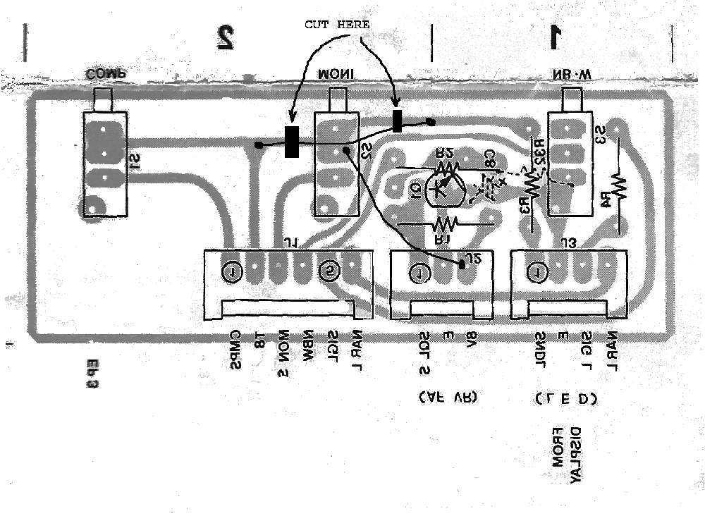
The board layout below shows the changes to make on the NB SW
board. The circuit board is shown looking at the bottom.
This board can be removed by just taking the top, bottom, and the
front panel off. It is the top board on the left as the front
faces you. Remove the connectors, depress all the switches, and
remove the three teeny tiny screws going into the top of each switch.
The bottom of the three switches have little flanges that hook
over the front of the chassis. You can tilt the board back and
slide it out toward the center of the rig. This keeps you from undoing
the front chassis and tilting it forward, although this makes it a lot
easier to remove the board.

Following are the steps I took to make the modification.
- Cut the circuit trace from the T8 lead J1 - Pin 2 going to the
monitor switch. I cut it between the "T" and the switch.
- Cut the circuit trace from the monitor switch to R3. I cut
it about 1/3 of the way between the switch and the pad where R3
connects.
- Put a jumper from the T8 trace to the R3 trace. You can
scrape the circuit board trace at the "T" and have a good place to
solder.
- Put a jumper from the monitor switch to J2 - Pin 3 (8V).
Audio Mute Modifications
I then started looking to see how to change the main board to keep
the audio line from switching when in cw mode. J12 - Pin 2 has a
7.5 V CW signal from the logic board. It is high only when in cw
mode, in all other modes it is low. I decided to use this to
control a relay that would hold Pin 6 of IC7 high when in cw mode and
reconnect it back to the squelch line when not in cw mode. An
OMRON G6K-2F-5 relay is very small and I could glue it to the top of
IC6 to hold it. This is a 5 volt DPDT relay. 7.5 volts doesn't
seem to hurt it and only one pole is needed. It is an SMT mount
relay and needs small wire. I used 28 ga wire wrap wire for all
of the connections.
The following are the circuit schematic changes made.
Following are the steps I took to make the modification.
(Steps 1 thru 5 are on the bottom of the main circuit board.)
- I cut the trace from Pin 6 of IC7 going to the collector of Q42.
- Connect a 6 inch piece of wire to the collector of Q42.
(Squelch line)
- Connect a 6 inch piece of wire to Pin 6 of IC7. (Electronic
switch control line)
- Connect a 12 inch piece of wire to Pin 2 of J12. I did this
at the W16 trace connection. (7.5 volts only in cw mode)
- Connect a 6 inch piece of wire to Pin 6 or 7 of J8. (Ground)
- Twist the wires together and bring them around the side of the
board near J8 and over to IC6.
- Mount the relay on top of IC6. (I used a small dab of hot
glue. RTV or something similar would work also.)
- Cut the the wire from the collector of Q42 to length, strip, and
solder to the Normally Closed (NC) contact on the relay.
- Cut the wire from Pin 6 of IC7 to length, strip, and solder to
the Moveable Contact of the relay.
- Cut the wire from Pin 2 of J12 to length, strip, and solder to
both the Normally Open (NO) relay contact and the plus side of the
relay
coil. NOTE: You can strip the wire long enough to go around
both contacts or use a separate jumper wire.
- Cut the wire from Pin 6 or 7 of J8 to length, strip, and solder
to the ground side of the relay.
- Firmly attach the relay to the rig. I used a small dab of
hot glue on the top of IC6. Hot glue can be removed pretty easily
if you need to do so. I would NOT use super glue!
When soldering to the traces, make sure there are no solder bridges.
The following are pictures of where the modifications go. The
first one is from the top side showing the general location of the
changes to be made. The remaining ones are looking at the bottom
of the circuit board, i.e. at the circuit traces.
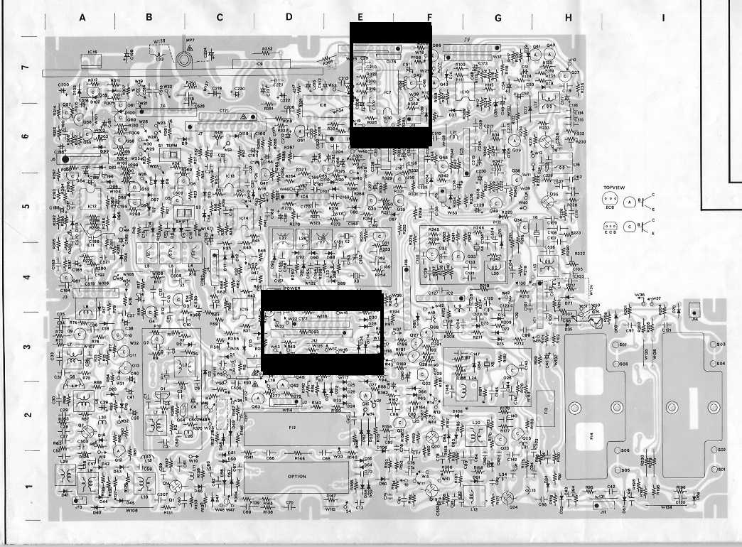
The board layout above shows the general location of the changes on the main circuit board.
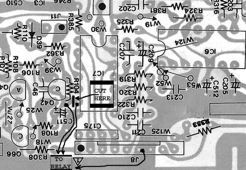
The board layout above shows the changes to be made around IC7.
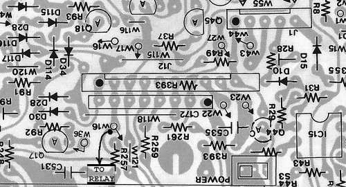
The board layout above shows the connection to make at J12.
You are now done! You will find the 751 almost noiseless in
full break-in mode. I know I enjoy using it on cw now almost as
much as the 761.
You will lose squelch in cw mode. I doubt this will bother
anyone. I have also noticed when the noise level is very high on
80 meters, like S9 or better, there are some spikes in the audio when
going back into receive mode. I don't know if these were
originally covered up by the thumping or what. You can reduce
these by reducing the RF gain to where the S meter is above the noise
level. I suspect the AGC is losing some voltage during transmit
causing the noise to appear loud at the time of switching.
This is not a simple modification. You need to be comfortable
working on circuit boards and confident in disassembling your 751.
A service manual is recommended.
|