This modification adds two lithium cells and diode steering to provide future fail-safe cell replacement. You will have to build a little breadboard with a couple of Schottky diodes and battery holders but the cost is way less than the shipping charge to send your rig back.
The ICOM IC-751 is my all time favorite radio. I haven't personally owned a lot of radios but I have worked on quite a few including Collins, Drake, Yaesu, Kenwood, Alinco, Heathkit, Icom, and many others.
What makes the IC-751 a nice radio for me is its clean, mostly discrete design with only a few high integration integrated circuits. It has a robust receiver with high input IP3 and well balanced gain.
The 751 uses real crystal filters and doesn't rely on any phony-baloney last-IF-stage-in-radio-pseudo
DSP for selectivity.
The front panel is intuitive and well laid out with a real meter, nothing I hate more than and LCD or plasm meter. There are real medium sized knows and push-button switches designed for real people's hands and fingers that make operating this radio a joy.
The transmitter is also an excellent design with separate, discrete and robust power amplifier section.
The 751 does not include an antenna tuner which I think to some degree is an advantage. For antennas that are not well matched, an external antenna tuner must be used. Generally, external antenna tuners are more efficient and always more reliable than internal antenna tuners and are very simple to maintain.
RAM battery scheme is a bit dubious. The original design requires the owner to send the radio back to ICOM every decade or so and have the lithium cell replaced. Failure to do so has left a number of owners with a brain dead rig and a conviction to never by another ICOM radio again.
Clearly it was a manufacturing expedience to use a battery backed SRAM instead of a more expensive EPROM for the program code plus an SRAM for the user memory. One can imagine that they could have socketed the lithium cell so that user could replace it while the radio was powered on. I suspect this idea was discarded because of possible product liability issues with having the operator change the cell with the power on.
This modification adds a small, home brew breadboard containing two replaceable 20mm lithium cells. Each cell can be replaced one at a time so that one cell is always powering the RAM. In addition, this modification leaves the original cell in place which greatly reduces the possibility of accidentally clearing the memory.
Modification instructions
This is a pretty simple modification and I think considerably safer to perform than the battery replacement method that Icom recommends. However, you do have to use above average care due to the risk of losing the program memory. If this happens the radio will not be able to tune the synthesizer and you will have to return the RAM board to ICOM for reprogramming.
You will not need any additional power supplies or batteries to power the RAM board during this procedure. The existing RAM board cell will keep the memory alive during this operation. You should be using a grounded soldering iron, however, to minimize the risk of static discharge altering the memory.
You will be working with rather close spaced traces on the RAM board and the only precaution you need to be aware of is to not allow the battery board leads, soldering iron, or tools to short the RAM board cell.
Step 1: Assemble the dual battery board as shown below and in the schematic shown in pdf. Use approximately 10 inches of twisted black and red AWG 26 hook-up wire to make the connection to the RAM board. Prepare the RAM board ends of the black and red wire by stripping back about 1/8" of insulation an tin the leads.
Note that the board has two 2mm mounting holes spaced approximately 35mm. This will facilitate mounting the board in the 751 chassis on the voice module mounting holes.
Test the completed board with a VOM to ensure that the diodes have be correctly installed.
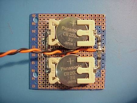 Note: Do not insert the lithium cells at this time. The cells will be inserted as the last step.
Step 2: Remove the bottom cover from IC-751 and pull out the RAM memory board.
Step 3: Carefully solder the negative lead (black) of the dual battery board to the RAM board ground trace at IC2 pin 7.
Step 4: Carefully solder the positive lead (red) of the dual battery board to the RAM board at the junction of diodes D1 and D2.
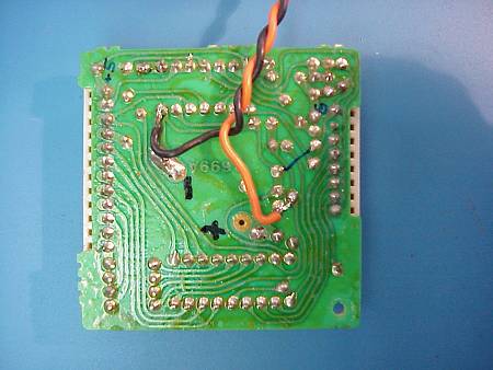
The RAM board connections should look like the photo above.
Step 5: Re-install the RAM board back into the 751. You can leave the dual battery board dangling outside temporarily.
Step 6: Monitor the voltage at the red wire on the dual battery board. You should see approximately 3.0 volts coming from the RAM board. Now, power on the 751, the voltage should now be approximately 4.8 volts if everything is ok.
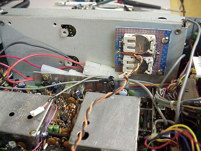
Step 7: Install the dual batter board in the 751 bottom chassis. I used the mounting holes reserved for the speech module. If you have the speech module installed you will have to look for a suitable location.
Fortunately, there is plenty of room in the bottom chassis to mount the board. I can't recommend using double sided foam tape as the adhesive usually fails after some time so its best to use screws.
Step 8: Turn the radio off and install the 20mm lithium cells in the holders. That's it, you're done.
You can now check conveniently check each cells voltage including the Icom RAM cell with your VOM. Just connect the negative lead of the VOM to the chassis and touch the positive lead to the top (+) side of each cell. You may notice that the memory RAM cell voltage is slightly higher than the new 20mm cells on the dual battery board. This is because the Schottky diodes have lower forward voltage than the diodes used on the Icom board. The 20mm cells are now powering the RAM and the Icom cell is floating.
In the future, when cell replacement is need, simply replace one cell at time and you will never have to worry about losing the RAM program.
|

