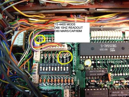
Problem: Limited transmit frequency coverage.
Fix: Cut D80 on the Control Unit for 1.6MHz to 30MHz transmit capability. D80 is about 2" from D66, which is cut for 10Hz frequency readout.
Problem: Lack of crispness in the RX audio, which makes the sibilant parts of human speech hard to distinguish from each other. This is caused by a p;5db roll-off at 3000Hz in the RX audio.
Fix: Change C51 [0.033µF] on the IF Unit, near L5, to .005µF [5000pF/5nF]. This will reduce the roll-off to a more acceptable p;1.4db at 3000Hz. "After modification, the RF Gain control should be backed off [CCW] until the band/sky-noise decreases to a comfortable listening level. This will not interfere with the reception of moderately weak signals.
Problem: Even while listening on a large, external speaker, music sounds flat and tinny because the audio frequency response rolls off below 200Hz.
Fix: There are a number of capacitors in the RX audio amplifier circuits that can be increased in capacitance to restore the low-end audio. These capacitors are in the IF Unit. They are: C60, C66. C67, C69, C170 and C175. The increase in capacitance should be 4 times. {Note: Some capacitors in
the audio circuitry can not be arbitrarily increased in value without causing unacceptable tradeoffs.} C175 can be replaced with a 1000µF, 10V unit, whose full-length leads are sheathed in Teflon sleeving, except for the last 8mm, to allow soldering to the PC board. This is done because the board-space allotment for the stock C175 is too small for the larger, replacement unit. The new capacitor is folded over and tucked in appropriately.
Problem: Tinny/thin-sounding transmit audio.
Fix On the IF Unit, change C135 {0.1µF}, near the center-board fastening screw, to 0.47µF.
Problem: The stock, muRata CFJ455K14 SSB filter in the 455KHz IF has a selectivity shape-factor of 2 to 1. This is definitely less than wonderful. The stock SSB filter in the TS-830S and TS-940S has about the same bandwidth at minus 50db, but it has a much better shape factor and it is mechanically and electrically interchangeable with the stock filter in the TS-440S. The better filter is a muRata CFJ455K12 or CFJ455V12, which will noticeably improve the transmit and receive, SSB audio quality of the TS-440S. This filter is available from Trio-Kenwood as p/n: L72-0333-05 for $42.89 {Dec 1989}. If you want SSB double-filtering in the 440's RX, the TS-940S' matching, 8.83MHz, YK-88-S1, 2.7kHz SSB filter is available from Trio-Kenwood as p/n L71-0222-05]. for $66.62 {Dec 1989}. This filter goes in the optional SSB filter space on
the IF Unit. For listening to an uncastrated-male voice, the YK-88-S1 will produce better-sounding, and more understandable, audio than the Kenwood-recommended optional YK-88-S, 2.4kHz filter. A pair of TS-940 SSB filters will give the 440 the same superb selectivity that comes with the 940.
Alignment: Supply a signal to the receiver. Set the TS-440S' selectivity
switch to M2, the single filter position. The USB and LSB carrier oscillators
[DIP switches on Control Unit] should be reset so that there is roughly
20db of RX, SSB carrier-suppression for each sideband at zerobeat. [use the 440's 20db ATTN as a standard] {Use 15db rolloff at zero-beat for more low-end audio, or 25db roll-off for more high-end audio and/or better unwanted sideband suppression} This completes the alignment of the carrier oscillators. >>> If you installed BOTH filters: on LSB tune the 440 above the calibrator's zerobeat frequency and note the 20db (or the roll-off db you used above) roll-off point. This should be around 3.1KHz, ±200Hz higher than zerobeat. Put this frequency & LSB into VFO B. Put the zerobeat frequency & LSB into VFO A. With the Selectivity switch set to M1 [double SSB filter], the 8.375MHz oscillator on the IF Unit is adjusted [TC2, in the lower left corner of the PC board] so that the improved skirt selectivity on the double filter position is equally distributed between the zerobeat 20db rolloff point [VFO A] and the high-frequency 20db rolloff point [VFO B]. The comparison can be done by watching the S meter and repeatedly pushing
the A/B button on the 440. [use fast AGC to reduce settling time] Note 1: TC2 is installed backwards on the PC board so that the rotor adjustment slot on TC2 is hot instead of grounded. This causes the capacitance of TC2 to change when a metal screwdriver is used to make the adjustment.
To fix this problem, TC2 is removed, reversed 180 degrees and re-soldered on the PC board. Note 2: see IF Unit schematic, CF2, the AM filter. There is a
1K Ohm resistor [R49] in series with the input [D13] to the filter. This
resistor provides a closer impedance match between the 2000 Ohm filter and
the source [L4]. A similar resistor can be installed in series with D12
at the input to CF1.
Problem: RX audio distortion. {This problem seems to be more prevalent in early production radios. There may have been a recent factory component change to reduce receive distortion.} There is one designed-in source of distortion and several other possible sources of distortion. The designed-in
source of distortion exists because not enough forward bias current is applied
to the switch diodes that select the SSB [D23] , AM [D24] , and FM [D25]
audio detectors. Here's why: A mixer is a nonlinear device. Nonlinearity
and distortion go hand in hand. Diodes make good mixers when their forward
current is in the range of 0.05mA to about 0.6mA. At currents above 1.5mA,
diodes are reasonably linear and they make good switches. The switch diodes
in the TS-440S have enabling currents of from 0.2mA for FM to 0.28mA for
SSB, so the switch diodes are operating in the region of maximum nonlinearity,
which results in distortion. The fix is simple: Increase the forward bias
DC-current through the diodes to roughly 2mA. This is accomplished by decreasing
the resistance of each DC-bias resistor to about 1k Ohm. When these resistors
are decreased in value, the 5000 Ohm impedance of the low-level audio circuits
decreases to about 500 Ohms and the values of the coupling capacitors must
be increased accordingly to prevent a rolloff of the low frequencies. Similarly,
the resistors that are in series with the audio signals in these circuits
must be decreased in value to offset signal attenuation. The capacitance
of the filter capacitors between switch diode bias resistors (for SSB: C52,
4.7µF) must be increased to compensate for the decreased value of the
bias resistors.
Fix for SSB audio detector and D23 switch: In the left, rear corner of the IF Unit, change: R71, R73, R74, and R85 to 1k Ohm; C53 to 47µF, 10V [XL=68 Ohms at 50Hz]; C52 to 22µF, 16V.
I'm guessing that similar changes can be made in the AM and FM detectors.
This project can become tricky since some of the needed changes can also
affect the transmit÷receive transition performance of the radio. Thus,
it may be necessary to compromise by lowering the switch diode bias current
to about 1mA. In general, this can be done by using 2k Ohm, instead of 1k
Ohm, bias resistors.
If, after the changes are incorporated, you can still hear RX distortion
on SSB, the problem may lie at the
[right-adjacent} product detector. Possible FIX: Install the missing injection-oscillator
terminating-resistor at the product detector. This resistor is 62 Ohm, 1/8W
or 1/4W. It is soldered under the IF Unit PC board, near L5. The terminating-resistor
is soldered to the junction of R69 and R70 and the ground foil at the edge
of the PC board. If the distortion persists, you may have an unmatched set
of Germanium product-detector diodes: D19, D20, D21, and D22. These diodes
can be replaced with Schottky diodes. The product detector balance should
then be checked and adjusted as follows: Connect an RF detector to the emitter
of Q9/R77. R77 sticks up from the board at one end so that the test connection
can be easily made. The RF detector can be an oscilloscope, detector/probe
for a DMM, or a 455KHz receiver coupled through a 10pF capacitor. With no
signal input to the ANT jack, turn the RF Gain on the 440 to zero. Set mode
to USB, IF Shift to detent. Adjust TC1 [also installed backwards, like TC2]
for minimum RF. End of test. Reset the RF Gain control to normal.
Problem: AGC overshoot while receiving strong SSB signals. The symptom is audio distortion on peaks only. The distortion is reduced when the RF-gain control is backed off.
Fix: On the RF Unit, near J13, near Q5, change R42 from 470k Ohm to 10k Ohm. This speeds up the attack response of the AGC.
Problem: TX frequency response is not the same as RX frequency response with the IF Shift control set on detent.
Fix: Connect a frequency counter to IF Unit, J26, pin 2 and ground. With the IF Shift on detent, the frequency [roughly 455kHz] of the carrier oscillator should not change between TX
and RX. If the frequency changes, adjust VR7 until the frequencies are equal. VR7 is just behind the MIC pot and the top of the front panel; it is mounted on a small, PC board.
Intermittents. The interconnecting wires in the TS-440S are copper. The tin-plated single-row connector pins that are crimped to these copper wires form a dissimilar metal junction that is subject to electrolytic action due to moisture in the air. Some of these crimp connections may eventually fail to provide electrical contact due to electrolysis.
Fix: Remove the defective connector pin by depressing the ratchet-tab in the slot on the side of the connector pin and pulling the freed pin from the connector body.
[The ratchet-tab can be depressed with a small screwdriver.] The copper wire that protrudes past the crimp is then electrically bonded to the pin with solder or Silver Print [GC Electronics] conductive paint. The wire/crimp junction should be inspected with a magnifier before the pin is re-inserted into the connector. If a wire/crimp junction is soldered instead of being dabbed with conductive paint, it is difficult to prevent the heat from melting the plastic insulation on the wire. If soldering is the choice, the rosin flux residue should be removed from the pin with alcohol, or acetone.
The same type of intermittent problem may also occur in the coaxial connectors. The fix is to apply conductive paint between the crimp on the center conductor pin and the copper wire.
An intermittent frequency display or wandering SSB receive frequency can be caused by a dirty socket-to-chip contact on IC52 in the Control Unit.
On later production radios, IC52 may be soldered in. The same symptoms can also be caused by a bad solder connection on R152 in the 36MHz VCO [VCO #5] at the front-center of the PLL Unit, near T20. Another common problem with VCO5 is L41 [10µH] which apparently suffers from an intermittent
internal connection. L41 is potted, so the best fix may be to replace it.
A very common problem with VCO5 is that the type of glue that is used to mechanically bond the components together appears to absorb moisture from the air (it is hygroscopic). Since water has a dielectric constant of 79, its presence can cause much grief in an RF circuit. Thus, the moisture that is absorbed into the glue can cause the oscillator to unlock.
Fix: Remove the original glue with solvent and a knife. If the glue is not replaced, VCO5 will exhibit microphonic problems. Some types of clear hot-glue seem to work well for replacing the original glue. Re-adjust VCO5 after the glue has set up.
Problem: No direct access to RX input or RX mute. These capabilities are necessary if the 440 is to be used as a slave-receiver in conjunction with another transceiver.
Fix: On the IF Unit, connect a wire from the base of Q39 to J22, pin 2. Remove R176, near J22. On the X41-1610-00, (M/14) Switch Unit at the rear of the 440, jumper across R46 [10K Ohm]. The RX will now mute when the FSK IN jack is grounded. {FSK TX is still possible if the AFSK is fed into the MIC jack through a 10 to 1 voltage divider.} The receiver input access can be brought out to the ACC 3 connector by connecting a 27 Ohm to 51 Ohm 1/4W resistor to J29, pin 2 on the X41-1610-00, (N/14 ) Switch Unit. A short length of wire connects the other end of the 1/4W resistor to the center of the ACC 3 jack which is now the RX input. When slaved to
another transceiver through the transverter port, this arrangement allows the operator to simultaneously listen on 2 frequencies with stereo earphones. This provides an advantage to the user when working DX on split frequencies.
Problem: There is no way to adjust the reference frequency oscillator with the case on. If the frequency is adjusted with the case off, the frequency will be different with the case on.
Fix: drill a 7mm to 8mm hole in the left side of the bottom half of the case. The hole should line up with TC1 on the PLL Unit. The position of the hole can be located with the case in place. The horizontal measurement is 122mm back from the edge of the front panel that wraps around the left side of the radio. The vertical measurement is 6mm below the edge of the top half of the case that overlaps the bottom half of the case.
To adjust TC1: [You must have 10Hz readout enabled] Tune to 10.00000 MHz WWV, USB or LSB. Select W [wide] on the selectivity switch. Wait until the tone modulation is present. You will hear both sidebands. If the 2 tones are not the same, adjust TC1 until the tones zerobeat.
Problem: On QSK and on SSB VOX, it does no good to back off the RF Gain control to reduce the nuisance of static crashes or band noise. This is because the factory stock receiver comes on full-bore whenever the TS-440S transitions from TX to RX - even if the RF Gain is backed off!
Fix: On the IF Unit, change R36, near Q5, to 2M Ohm; change R60, near Q7, to 510K Ohm. ± a few standard values will make little difference.
Problem: Your own transmit RF gets into the TS-440S through the EXT SP jack and causes audio rectification that is heard in the external speaker.
Fix: The sleeve/shield terminal on the EXT SP jack should be bypassed to ground on the (G/14) Switch Unit with a 2nF to 20nF, 500V, disc ceramic capacitor.
If the problem is most severe on 10 meters, try 2nF [.002µF]. If the trouble is most severe on 80m or 40m, try 20nF [.02µF].
Problem: You can hear distorted audio coming out of the internal speaker while you are transmitting on SSB.
Fix: Remove the top cover on the radio and re-position the internal speaker wires away from the area around the SSB filters. The speaker wires should be confined to the area around the speaker plug on the IF Unit. Also, keep the speaker wires away from the Control Unit behind the digital display.
Problem: Key-clicks on CW. This is caused by too fast (500µS) RF output rise [make] and fall [break] times.
Fix: On the IF Unit, change C168, near Q49, to .22µF; change R225 to 33K Ohm-43K Ohm. {the factory's "fix" for this problem is OK on make but it still clicks on break}. Unfortunately, fixing the key-click problem also seems to affect the full breakin make timing in the 440 which clips the first dit. Thus, if you want to use the 440 on full, instead of semi, breakin, you must put up with the key-clicks.
Problem: The amplifier-keying-relay, RY2 on the (N/14) Switch Unit, makes too much noise, or the contacts on RY2 have burned and pitted, or all of the above. Another problem with RY2 is that it is too slow to use with a full-QSK amplifier. This needless make-delay can cause the amplifier to hot-switch, burning the contacts in its QSK-relays.
Fix: replace RY2 with an NPN switching transistor and fix the current pulse problem that pitted the relay contacts, which may also damage the transistor. [only works for amplifiers with positive voltage relay control]. If your amplifier uses positive 110V for the relay control, like the SB-220 and the TL-922, the relay pitting is caused by the current pulse from the repeated shorting out of the charged .02µF bypass capacitor across the amplifier's relay control jack. The bypass-capacitor can be removed if shielded wire is used for the interconnection cable to the transceiver. Another fix is to install a 150 Ohm to 200 Ohm, 1/4W series resistor at the relay control jack to limit the discharge current to a value that the relay or switching transistor can handle. The bypass capacitor is connected to the relay-side of the resistor.
Transistor Installation Notes: The N/14 Switch Unit is located just behind the ANT RF connector on the rear panel. The small access panel on the bottom, rear of the radio is removed to gain access to the N/14 Switch Unit. Two chassis-ground connections and one center pin connection must be unsoldered from the RF connector before the Switch Unit can be removed.
Unplug the three connectors, remove the two sheet metal screws, and lift out the Switch Unit. Unsolder and remove RY2, D16, and the white jumper-wire and the pin that it plugs into. Install one 1k Ohm resistor each in place of D16 and in place of the jumper-wire and its pin. The transistor will solder in place of the relay if its full length leads are bent to fit the available holes. The emitter goes to common-ground, as does the trace to J30, pin4 [CMC], the ground return for the relay control circuit. The base lead connects to the trace that goes to R2 {D16} and C37. The collector solders to the trace that connects to J30, pin 2 [TXC].
Problem: Poor skirt selectivity on AM.
Fix: The unsatisfactory, stock, TS-440S AM filter, CF2, can be directly replaced with the better performing, AM-narrow, 6KHz filter from the Trio-Kenwood R-1000 receiver. The part number of this filter is L72-0319-05 and the price is $9.10 {Dec 1989}. It is available as a replacement part. Even though the better filter has more pin connections and is physically larger than the original filter, the IF Unit printed circuit board was designed to accept either AM filter. The design engineers must have realized that some people would want to install a good AM filter.
CF2 is a small, black, cube-shaped plastic component at the rear of the IF Unit just slightly to the right of left-to-right circuit board center. No realignment is necessary after the AM filter is replaced. Maintenance: The VFO tuning knob should be removed, after loosening the 1.5mm hex-socket set-screw, and the tuning shaft's bushing-bearing should be lubricated with a modern semi-synthetic lubricant like Break Free or Tri Flow. The quantity of lubricant used should be small and the radio should be tipped back to help the lubricant run down into the bushing-bearing. This should be done once when the radio is new and roughly every 4-years thereafter.
Double-sideband modification for the TS-440S
Occasionally, it may become advantageous to use double-sideband-transmit and single-sideband receive mode in order to thwart the efforts of radio sociopaths who are gratified by interfering with others. DSB-xmit/SSB-RX mode gives the non-interfering stations the option of listening to the sideband that has the least amount of interference.
To install DSB capability in the TS-440S, the audio processor switch is rewired so that when the switch is depressed, the carrier is removed from the AM transmit signal. Without a carrier, AM becomes DSB. {The DSB modification will disable the less-than-worthless audio-PROCessor in the TS-440S.}
The modification: On the IF Unit [the top board] locate R179, which is between IC4 and Connector 21 at the front, left of the circuit board. Remove R179 and connect a jumper wire from the right hand, empty solder-pad hole on the circuit board [collector of Q41] to the junction of D45 and R196, which is straight back on the circuit board, just to the left of IC5; about 4cm from the rear of the circuit board.
To enable DSB transmit/SSB receive, "SPLIT" operation is utilized:
- Program VFO A=B.
- Program VFO A for either USB or LSB, depending on which one has the least interference.
- Program VFO B for AM and push the PROC [DSB] switch in to remove the AM carrier.
- Select VFO A.
- Program SPLIT operation. The 440 will now listen on VFO A and transmiton VFO B.
- Set the carrier control straight up to position #5 [12 o'clock].
- While transmitting, adjust the MIC gain control for a small amount of ALC. This keeps the DSB bandwidth to a minimum.
While listening [VFO A], it may be necessary to select the sideband that has the least amount of interference. If your friends are also transmitting on DSB, you may be able to continue communicating, despite the efforts of those who would like to spoil the enjoyment of others.
>>>DSB should not be used unless the other sideband is vacant. If the interfering station or stations can cause the group that they are interfering with to interfere with a third group, it will definitely make their day.
Most jammers enjoy being talked about, either positively of negatively. This is why they usually switch back and forth between receive and transmit. If you want a jammer to stick around, talk about him. Stupid insults usually work best.
|

