The ICOM 756PRO documentation is silent when it comes to describing
the CW filter shape factor, and how it can be selected. ICOM tried to improve the
situation with a brief mention of this topic in its Advanced Operation Guide for the 756PRO, but it does not clearly describe how to select the filter shape. I will try to do a little better on this page. I would like to thank Rob Peebles, W8LX, for bringing these capabilities of the radio to my attention.
The 756PRO receive audio, coming out of a digital signal processing (DSP) intermediate frequency (IF) stage, is much different in character than other purely analog receivers.
On CW, the filter response created by the DSP is extremely sharp. That is, signals outside of the passband are substantially attenuated. In the analog domain, sharp filters can lead to ringing, and other artifacts. Digital filters can have similar problems. In addition, it has been claimed that the 756PRO receiver highlights flaws (key clicks) in the transmitted signal. In other words, it hears the clicks better than other receivers. These various factors lead to CW receiver performance which some operators do not like. One suggestion to improve performance has been to alter the CW filter shape. Perhaps if the filter was not as sharp, the artifacts would not be as pronounced. Apparently a special DSP ROM (software) is available in Japan, but information on this modification has been difficult to obtain, and in any case, changing the DSP software is claimed to be a major project, in terms of taking apart the radio to access the relevant parts.
It turns out that for filter widths of 500 Hz and less, it is possible to select one of two filter shape factors. One is the sharp CW filter, and the other appears to be the SSB shape factor, which is not as sharp. Calling one the CW shape factor and the other the SSB shape factor is my own terminology. Rob Peebles, W8LX, estimated the sharp CW shape factor to be 1.5, and the SSB shape factor to be 2.0. This page describes how to select the two different shape factors (in the CW mode, it cannot be selected in SSB mode).
The top line of the main display contains a yellow indicator labeled BPF. This indicator is not mentioned in the documentation (756PRO user's manual). It appears immediately to the right of the passband width indicator (page 10 of my manual). It is my belief and claim that this indicator shows the IF filter shape factor state. When the indicator is off, the display is dark, the SSB shape factor is in use. When the BPF characters are visible, the CW (sharp) shape factor is being used.
Early 756PRO users discovered the BPF indicator soon
after the radio was introduced. It was clear that it was tied to the CW filter width. As
best as I can tell, you must be in CW mode in order to be able to use the sharper
filter. When the CW filter width is set to 500 Hz or less, via the BW (F-1) button, in IF
filter selection mode, the BPF indicator and mode automatically turns on.
Until I talked to Rob Peebles, W8LX, I assumed that all CW filters 500 Hz or less in width
would have the BPF indicator on. This turns out to be untrue. It is
possible to have CW filters at and under 500 Hz without having the BPF
indicator on. Since the BPF indicator is not on, you will be using the
SSB shape factor, even if the filter width is reduced to the minimum value of 50 Hz.
The current filter width and shift (offset) are displayed on the top line
of the main display. The BW field indicates the filter bandwidth, and the
SFT field indicates the filter shift. I believe that these two fields,
along with the BPF indicator, completely capture the IF filter state of
the radio. There is no more data to view or change.
There are two different ways to specify the filter width.
Until this issue came up, I assumed that both ways would always arrive at identical
results. This is not true. One way changes the BPF indicator and the
other does not. Again, this discussion applies to CW mode. In SSB mode, the BPF
indicator will never turn on.
The first way to adjust the IF filter width is to use the BW [F-1]
button in conjunction with the main VFO knob. You must enter the IF filter set mode in
order to use this way. When this way is used, the BPF indicator will turn
on for all widths of 500 Hz or less.
The second way to adjust the IF filter width is to use the Twin
PBT knobs. These concentric knobs can be adjusted to narrow the filter width.
Here is the entire point of this web page: When the IF width is adjusted with the
Twin PBT knobs, the BPF indicator will not come on, even for widths equal to and under 500
Hz. Obviously you must start with a width greater than 500 Hz so that the PBT indicator is off to begin with.
My own opinion is that this is a bug that really
is a feature. My guess is that ICOM engineers wanted the sharp CW filter to be on
for all widths of 500 Hz or less. When using the BW button, it works like
that. But when the Twin PBT controls are used, the check for crossing the
500 Hz boundary is not made, and the filter does not change shape.
The best way to evaluate the two different filter shape factors is to A/B
compare them for a constant filter width. Here's my suggestion for doing that.
Pick a band like 40 meters that usually has a number of CW signals, and
some background noise (especially at night). Set the 756PRO to CW mode, and enter the filter set mode by pressing the
Filter button for 2 seconds. Select the first filter and press the DEF button to
return the filter to the factory default width of 1.2 KHz. Since this width is greater
than 500 Hz, the BPF indicator will be off. Turn the outer Twin
PBT knob to the right 10 clicks. Turn the inner Twin PBT
knob to the left 10 clicks. This should result in a 200 Hz filter. Since the
filter was narrowed with the Twin PBT knobs, the BPF
indicator should still be off. You now have a 200 Hz wide filter with the SSB shape
factor. Select the second filter and press the DEF button to
return the filter to the factory default width of 500 Hz. Since the filter width is 500 Hz
or less, the BPF indicator will be on. Press the BW
[F-1] button and while holding the button, rotate the main VFO knob to the left until the
width reduces to 200 Hz. You now have a 200 Hz wide filter with the CW shape factor.
You now have two filters with identical widths, but with the two different
shape factors.
Tune around the band, and use the Filter button to select
the different filters.
Remember, when evaluating filters, check the BPF
indicator state. When BPF is on, you are using the sharp CW filter shape.
When the indicator is off, you are using the broader SSB filter shape.
So, is this a distinction with a difference? While the difference is not
large, my own subjective opinion is that it significant. The SSB filter shape sounds much
more like traditional filters in an analog IF radio. The CW signal edges are not as sharp
and grating. The sound is a bit softer. Even the background noise of the band
changes. I could imagine that it would be much less tiring on the ears to listen to the
SSB filter shape for extended periods. In contest situations, however, with crowded bands,
the CW filter shape will probably be more desirable.
Your mileage may vary.
With appropriate test equipment it would be possible to make a more
accurate estimate of the shapes of the filters. Although I don't have that equipment, I do
have the program Digipan, which is PSK31 software with an integrated audio spectrum analyzer. Here is a Digipan screen capture
showing three filter choices.
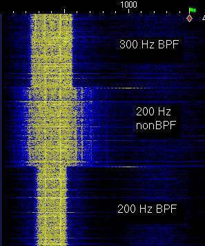
Digipan Display of Selected Filters
The Digipan screen capture shows the audio spectrum output of three
different filters. The capture was made on a noisy 80 meter band, monitoring background
noise. My CW center frequency was 400 Hz. Since the program scrolls from top to bottom,
the first filter selected is actually at the bottom of the captured screen. The bottom
filter is a 200 Hz filter with the CW shape factor (BPF is on). Note the
sharp edges, indicated by the straight vertical lines that separate the black (no output)
zone from the yellow zone (random background noise coming through the filter). Above the
200 Hz BPF filter is the 200 Hz nonBPF (SSB) filter. The
edges are no longer as sharp. Additional energy around the 200 Hz width is coming through
the filter. The blue lines indicate intermediate energy levels (between yellow and black).
Finally, the top and last filter is a 300 Hz BPF filter.
Larry Benko, W0QE, a 756PRO user who independently discovered the two CW
filter shapes, informed me of another program, Spectrogram, which is a free audio analysis tool. I used Spectrogram to create spectrum plots of the 200 Hz wide BPF and nonBPF CW filters. These screen captures, made while listening to the same noisy 80 meter band, reveal the different filter shapes.
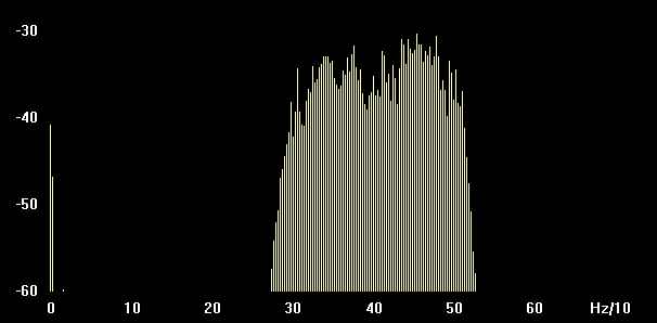 |
200 HZ BPF filter (CW shape) |
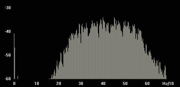 |
200 Hz nonBPF filter (SSB shape) |
The nonBPF filter shape factor does have a character all
its own. In some circumstances, you may find it useful, and at the least, ICOM should
document it.
The use of a broad-band uniform RF noise source, such as 80 meters at
night, combined with an audio spectrum analyzer implemented in software on a computer, is
a simple but effective approach for making reasonable measurements of receiver filter
passband characteristics. These plots compare the ICOM IC-756PRO against the ICOM IC-765.
|

